Voltage-triggered switch with latch
Voltage-triggered switch / battery disconnect
This circuit will switch a 9-24V DC load device on when the supply voltage rises above an adjustable threshold, and switch the device off when the supply voltage falls below another, lower adjustable threshold. The intended purpose of this for use with solar power - it can disconnect a load when the battery voltage is too low, and reconnect the load only when the battery is sufficiently charged.
This is a very common component within a solar power system, and ready-built modules for this purpose are readily available. I just wanted to build my hobby scale solar from scratch using all my own designs, and this circuit has some advantages - it's compact, can be built as a hobby project on stripboard, and is all solid-state with no relay. It runs off 2mA, less current than is needed just to energise a relay coil. It will operate from 9 to 15V, and with a simple alteration to the voltage divider it can operate up to 36V - enough margin for a 24V-nominal battery system
A single voltage threshold would not suffice for this application - the load might be switched rapidly as the battery is alternately charged and discharged leading to improper (or in the case of lights, annoying) operation. Such a circuit would also be prone to oscillation as connecting a heavy load might cause the supply voltage to fall sharply, below the turn-off threshold, leading to immediate turn-off - and turn-on moments later as the battery quickly recovers. At worst it might even settle in such a way that the power MOSFET gate voltage is insufficient to fully turn on. Using an upper and lower threshold with a simple latch avoids these problems.
This circuit was constructed for a solar-powered garden lighting system to prevent the batteries from draining during a period of prolonged poor weather. On a larger solar power system it would also be potential use for load shedding - as different devices could be set to different thresholds it would be possible to, for example, shut down an ornamental fountain as soon as the battery voltage falls below a near-full level in order to conserve energy for more critical applications.
As well as the intended application for use in solar power, the circuit has a low current draw (approx 2mA, if using a low-quiescent regulator rather than a 7805 or zener), and so may be of use in energy harvesting applications. For example, a small solar panel or other low-power source could slowly charge a battery or supercapacitor. When sufficient energy has been accumulated a power-hungry load such as a water pump can be turned on, and turned off when energy is depleted so the cycle may continue, moving water a little at a time. In this manner a steady, low-power source of energy may be easily used to operate an intermittent, high-power load according to the amount of energy available in the optimally efficient manner.
The voltage reference can be either a common 7805, a zener diode and bias resistor, or a low-quiescent-current regulator like the LM2936. If you want very precise voltage control with excellent thermal stability you could also use a dedicated 5V reference like a MAX675, REF02CPZ or LT1027, but this would be more expensive. The choice is determined by two factors: Acceptable current use for the switching circuit, and the contents of your parts cupboard. I suggest the LM2936, but if you don't mind the 5mA current consumption of a 7805 it'll work just as well. A 5.6V zener diode, for comparison, needs 1.2mA with a 5k resistor.
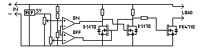
The comparator is an LM393. This is not a conventional amplifier, but a dedicated comparator chip with open-collector outputs. One LM393 has two comparators, making it ideal for this circuit. It will also operate over a wide supply range, up to 36V. The open collector outputs are ideal for connecting directly to the RS latch.
The circuit employs a simple RS flip-flop latch constructed using two BS170 FETs and pull-up resistors - the exact value is not important, anything from 10KΩ to over 100KΩ will work equally well, though lower values will slightly increase current draw. This in turn drives an FB4710 power MOSFET to switch the load, though many N-channel MOSFETS are suitable for this. If you want to use a P-channel, just switch the gate to the other BS170 to invert it. The resistor in between is required to protect the more delicate electronics of the BS170 and LM393 from spikes coupled through gate capacitence. Exact value is again unimportant, anything from 10KΩ to 100KΩ.
The voltage divider must be constructed to a 2:1 ratio (5:1 for a 24V system), but substitution will pose no difficulty so long as ratio is correct and the total is sufficiently high not to draw significant current. If you are using a zener as your voltage reference than the potentiometers should be at least 50KΩ, ideally 100KΩ, as such a reference can supply very little current.