THAT: Lorenz Attractor
published 2026-01-15
by Christopher Howard
During the lunch break, I setup the Lorenz Attractor circuit, one of the example circuits in the THAT manual. I find that the easiest way to setup these example circuits is not to duplicate the patch panel diagram, but rather to make a copy of the analog circuit diagram, and then to work through making those connections. I highlight each connection line, after making the connection, and then I highlight the component after all the connections for that component have been completed.
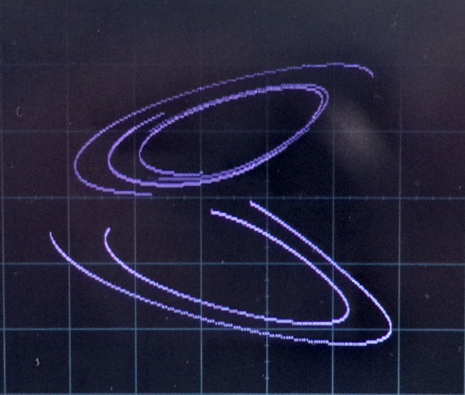
I found that the recommended coefficient settings did not work on my system. I.e., the solution I got was simply the signals quickly dropping to zero. But after fiddling with the pots for a while, while watching both signals on the scope, I figured out a working set of values. This is the view of the attractor I got in XY mode:
scope output of Lorenz Attractor in XY mode, with averaging
The visual result does not look as nice as the usual pictures, unfortunately. My scope does not have the ability to change the persistence value of signal points on the screen. I can change the intensity, i.e., the fake brightness of the signal point, but not how long the point remains on the screen. I turned on averaging, which makes the curves appear more crisp. Also, I had to take a photo of the LCD screen, because the screenshot function only captures a small fraction of the curve that is shown in the camera's exposure time.
My view of the attractor is a result of using fast repetition mode (REPF). I found that if I extend the simulation out to longer times, with REP mode, that the attractor always collapses to the origin after a few seconds. Presumably this is due to dampening in the system, or perhaps from the coefficients being incorrect or unstable.
Copyright
This work © 2026 by Christopher Howard is licensed under Attribution-ShareAlike 4.0 International.