Square Function with Diode Network
published 2026-02-12
by Christopher Howard
I would like to see if I can set up a simple flight model on my THAT that calculates horizontal-and-vertical lift, drag, acceleration, and velocity, based on adjustable Angle of Attack and thrust inputs. I scribbled out a simple model for this, making many simplifying assumptions such as: straight flight (no banking); mass remains constant (frozen fuel); and air pressure does not change with altitude.
One of several obstacles to this is that numerous multipliers are needed, related to the calculation of the lift and drag, which both need the square of velocity as an input. The simple, and most sensible, trick is to get the square of a voltage is to feed the same input twice into the same multiplier. But THAT comes with only two multipliers. How to get around this? One idea is to buy another AD633 multiplier chip, and build a small expansion board. However, the AD633 chips are about 20 USD each, which is a lot on my tight budget. There are a few other less expensive chips out there which can produce a product of a signal, but they generally are intended for different use cases — for example, manipulating radio signals — and I am hesitant to buy any of these chips to experiment with them.
Another approach is to do approximation with a diode-resistor network, plus a few op amps. I have a lot of resistors and signal diodes, and a lot of 741 op amps, so — wisely or unwisely — I decided to give this a try.
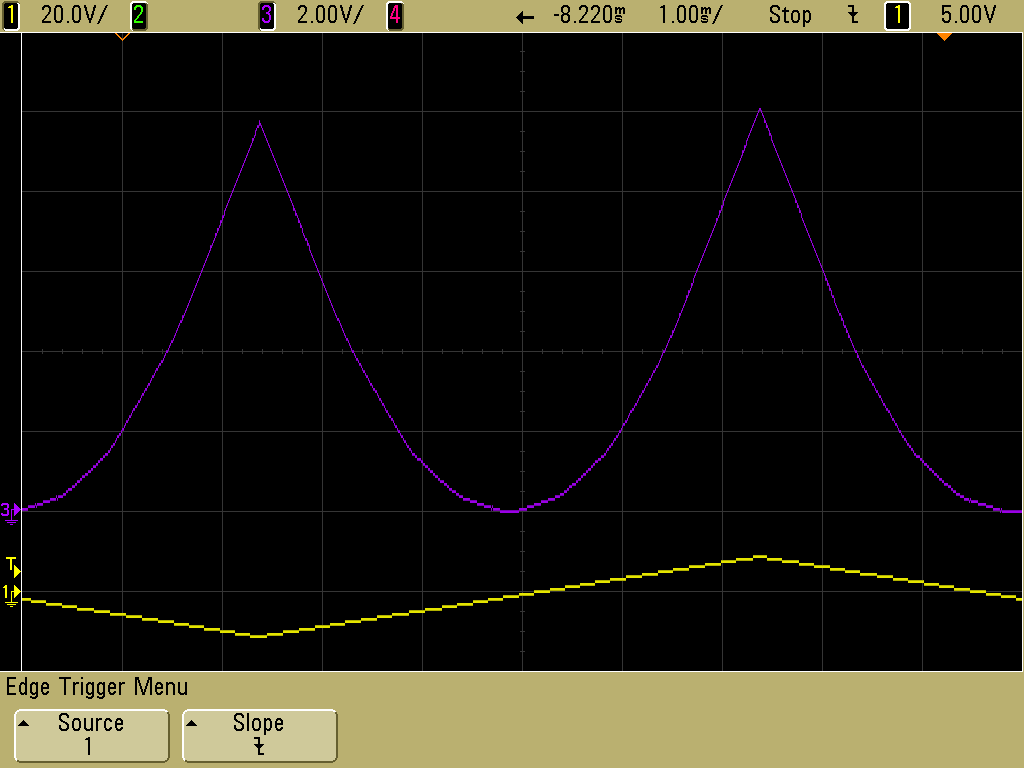
The process of building a custom function with diodes, I must say, is not a quick and easy process, unless you have one of those fancy variable function generators with a bunch of potentiometers and switches. I don't currently have one of those, though I am thinking I might build one later. The basic process I used was to sketch out a schematic on paper, one line segment module at a time, with estimated resistor values, and then to add that module to the breadboard, testing and adjusting resistor values as necessary. This took quite some time, as you might imagine, but I did successfully complete a ten-segment approximation of the square function. Or, more precisely, f(x) = x²/10. The output must be one-tenth of x² in order to keep the output values within the +/- 10V range.
Here is the scope output, where the +/- 10V input (scaled down) can be seen at the bottom, generated with a ramp function. At the top is the output signal, shown at a larger scale for clarity.
Here is the scribbled out schematic:
Here is the breadboard:
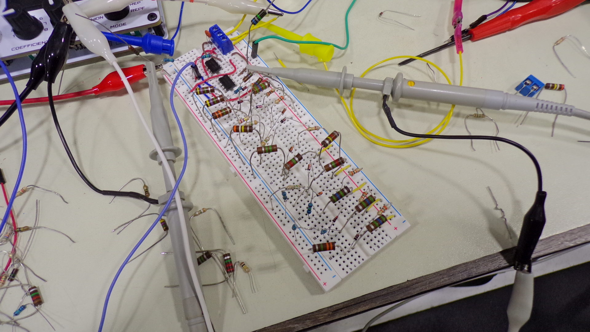
I don't want to keep using that circuit on a breadboard, which would be problematic for multiple reasons. But I think it might be too much pain and suffering to try to wire it up on a protoboard. A printed circuit would be nice, though that would cost a similar amount to buying the multiplier chip. So I'm not sure where I'll go from here.
One oddity I ran into multiple times, while building the circuit, is I find suddenly that my output had a big positive voltage offset, like +7 volts. Generally, I found that if I removed the second stage op amp, and replaced it with another, that the problem would disappear. ESD damage?
Copyright
This work © 2026 by Christopher Howard is licensed under Attribution-ShareAlike 4.0 International.