Basic rendering tutorial with Radiance
[Radiance] is *the* authoritative validated rendering engine out there. Unlike other rendering engines, which focus more on artistic license, Radiance focuses on scientific validation -- that is, the results are not just *physically based*, they will produce the exact same output as measured by a physical optical sensor. This is great if you'd like to produce an image that not only looks photo-realistic, but actually matches what a similar setup in real life would look like. As you'd expect, this appeals to scientists, and designers who work with light and materials.
In addition, Radiance is open-source, completely free, and is [Unix-like]. If you've used other tools that claim to do all of the above, it probably uses Radiance under the hood anyway and rebrands itself with a more friendly interface. However, working with Radiance directly will give you a finer grain of control over the image you produce, and as I will likely write about in the future, scale up to do highly complex renders. Today, we're going to dive into the guts of the tool itself and render a simple object. This can be a bit scary to those who are not particularly technical, and there's not a lot of friendly material out there that doesn't look like it's from a 1000-page technical manual. Hopefully this walkthrough will focus on the more practical aspects without getting too bogged down in technicalities.
To begin, I'm also going to assume you have Radiance installed, and know how to open up a terminal window in your operating system of choice. If you haven't got that far yet, go and install something simple like [Ubuntu Linux] and / or [install Radiance]. Radiance is not a program you double click on and see a window with buttons and menus that you can click on. Radiance is a collection of programs that work by typing in commands.
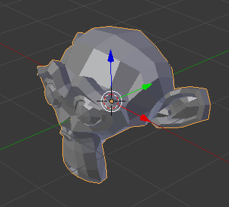
Let's create a model first. Start with a simple mesh with a minimum of polygons. I am using [Blender], which is a another open-source, free, and Unix-friendly software. In this case, I have started with a default scene, and arbitrarily replaced the default cube with a mesh of the Blender monkey mascot. I have also given the mesh a material, named `white`.
Default scene with Blender monkey
Using Blender is optional, of course, and you can use whatever 3D program you like. Radiance works with the [OBJ format], which is an open format, plain text, and beautifully simple. As such, export the mesh to get yourself a resultant OBJ file, of which I have named `model.obj`. The exported accompanying `model.mtl` file is largely unnecessary right now: we will define our own materials with physical units, of which the `.mtl` file is not designed to do. When exporting, take care to only export the mesh, and ensure that the proper axes are facing up.
In the same directory that you have your `model.obj` and your `model.mtl`, let's create a new file which will hold all the materials for your model. In this case, there is only one material, called `white`. So let's create a new plain text file, called `materials.rad` and insert the following in it:
It's the simplest possible material definition (and rather unrealistic, as it defines an RGB reflectance value of 1, 1, 1), but it'll do for now. You can read about how "plastic" (i.e. non-metallic) materials as defined in the [Radiance reference manual]. In short, the first line says we are defining a plastic material called white, and the last line says that there are 5 parameters for this material, and their values are 1, 1, 1, 0, 0 respectively. The first three parameters refer to the R, G, and B reflectance of the material. This definition is provided in the Radiance manual, and so in the future it will serve you well to peruse the manual.
Now, open up a terminal window in the same folder where you have the `model.obj` and `materials.rad` file. We are going to run a Radiance program called `obj2mesh` which will combine our OBJ with the material definitions we have provided in our `materials.rad`, and spit out a Radiance triangulated mesh `.rtm` file. Execute the following command:
If it succeeds, you will see a new file in that same directory called `model.rtm`. You may see a few lines pop up with warnings, but as long as they are not fatal, you may safely disregard them. This `.rtm` file is special to Radiance, as it does not work directly with the OBJ format.
Now, we will create a scene in Radiance and place our mesh within it. There will be no other objects in the scene. Let's call it `scene.rad`, a simple text file with the following contents:
The first line simply defines a new mesh in the scene called `model`. The second line tells it that it can find the mesh in the `model.rtm` file. The final line (the zero) says that there are no parameters for this mesh.
Now, we will convert our scene into an *octree*, which is an efficient binary format (as opposed to all the simple text files we've been writing) that Radiance uses to do its calculations. We will run another Radiance program called `oconv` to do this. So open up your terminal window again and execute:
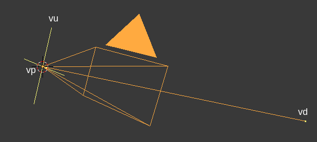
You should now find a `scene.oct` file appear in the same folder as the rest of your files. This is the final file we send off to render. But before we do this final step, we will need to decide where our camera is. A camera in Radiance is defined by three parameters. The first parameter, `vp`, or *view position*, is the XYZ coordinate of the camera. The second parameter, `vd`, or *view direction*, is the XYZ vector that the camera is facing. The third parameter, `vu`, or *view up*, is the XYZ vector of where "up" is, so it knows if the camera is rotated or not. When specifying a parameter to Radiance, you will prefix the parameter name with a hyphen, followed by the parameter value. So, for a camera at the origin facing east (where +X is east and +Z is up), I can tell Radiance this by typing `-vp 0 0 0 -vd 1 0 0 -vu 0 0 1`.
Calculating these vectors is a real pain unless your camera is in a really simple location and is orthogonal to the world axes like in my previous example. However, here's a fancy script you can run in Blender which will calculate the values for the camera named `Camera`.
The output will be in the Blender console window. For those on other programs, you've got homework to do. Note that this script is for Blender 2.80. For Blender 2.79 and earlier, use the `*` multiply symbol instead of the `@` PEP 465 binary operator for multiplying matrices.
Once you know your coordinates and vectors for `vp`, `vd`, and `vu`, let's use the `rpict` Radiance program to render from that angle. Please replace my numbers given to the three camera parameters with your own in the command below. We will also specify `-av 1 1 1`, which tells Radiance to render with an ambient RGB light value of 1, 1, 1. Of course, in real life we don't have this magical ambient light value, but as we haven't specified any other lights in our scene, it'll have to do. We will also specify `-ab 2`, which allows for 2 ambient bounces of light, just so that we have a bit of shading (if we didn't have any light bounces, we would have a flat silhouette of our monkey).
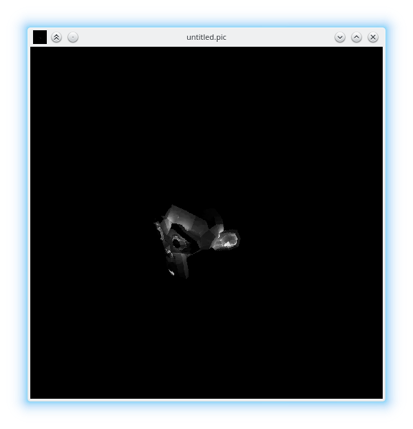
Great, after the render completes, you should see a new file called `render.pic` in your folder. Let's look at this image using the Radiance `ximage` program.
You should see something like the following:
One final step. It's quite irksome and technical to run all of the commands for `rpict`, `oconv` and such, and so it's much better to use the *executive control* program `rad`. `rad` allows you to write the intention of your render in simple terms, and it'll work out most of the technical details for you. Of course, everything can be overridden. The `rad` program parses a `.rif` configuration file. I've included a sample one below, saved as `scene.rif`:
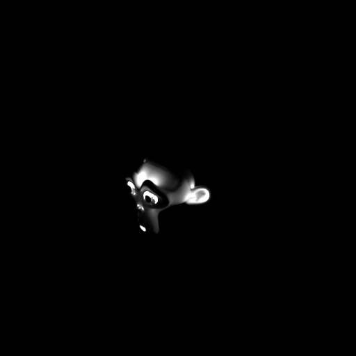
Execute `rad scene.rif` to get the results. If you'd like to interactively render it, on an X server you can run `rad -o x11 scene.rif`. I used the above `.rif` file and ran it against a higher resolution mesh, and I've included the results below.
All done! We've learned about bringing in an OBJ mesh with Radiance materials, placing them in a scene, and rendering it from a camera. Hope it's been useful. Of course, our final image doesn't look exactly great
- this is because the material and lighting we have set are basically physically impossible. Similarly, the simulation we've run has been quite rudimentary. In the future, we'll look at specifying a much more realistic environment.
You can see a git repository which shows all of this set up [here], which you can download for your convenience.